USING A MOTION SENSOR TO TURN ON A LIGHT (and keep it on)
The goal of this tutorial is to use a PIR sensor to detect movement in a plaza, then turn on a secondary system (in this case, just an LED light). The key thing here is not to detect every single movement, but to turn on the light and keep it on until the PIR detects no movement for a certain period of time, at which point the light should turn off.
The parts you’ll need for this tutorial are:
Parts:
- PIR motion sensor
- Arduino UNO
- 3 pin stacking header
- Jumper wires + resistors
- LED light
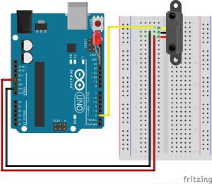
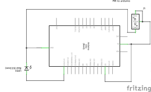
Here’s how to set up your breadboard (and resultant circuit):
The PIR sensor has 3 pins, which should be labeled. On our PIR, the pins read
“VCC,” “OUT,” “GND” from left to right on the botton of the plate.
Connect the PIR into the breadboard so that (–) pin connects to the Gnd row,
(+) pin connects to 5V, and Out pin connects to digital pin 2.
To test the sensor, plug the (+) pin of a red LED into pin 13 and connect the (-)
pin to GND
Now to put in the code. Again, the important thing here is that we don’t just want the PIR sensor to measure motion, we want it to reflect when a space is active and keep the LED on for as long as there is activity in the space. So, we have to set a minimum period of time after for the PIR to take measurements finding no motion, and then to turn off. In the code, this period is 10 seconds, but you can change it if a longer or shorter amount of time seems more appropriate to you.
|
1 2 3 4 5 6 7 8 9 10 11 12 13 14 15 16 17 18 19 20 21 22 23 24 25 26 27 28 29 30 31 32 33 34 35 36 37 38 39 40 41 42 43 44 45 46 47 48 49 50 51 52 53 54 55 56 57 |
/* USING A MOTION SENSOR TO TURN ON A LIGHT (and keep it on) Hardware connections: PIR Sensor The PIR sensor has 3 pins, which should be labeled. On our PIR, the pins read "VCC," "OUT," "GND" from left to right on the botton of the plate. Connect the PIR into the breadboard so that (–) pin connects to the Gnd row, (+) pin connects to 5V, and Out pin connects to digital pin 2. To test the sensor, plug the (+) pin of a red LED into pin 13 and connect the (-) pin to GND This tutorial was written with the help of Kristian Gohlke from http://playground.arduino.cc/Code/PIRsense and John Edgar Park from http://makezine.com/projects/PIR-Sensor-Arduino-Alarm/ and https://learn.adafruit.com/pir-passive-infrared-proximity-motion-sensor/using-a-pir */ //VARIABLES //the time we give the sensor to calibrate (10-60 secs according to the datasheet; we'll give it a minute to be safe) int calibrationTime = 60000; //the time when the sensor outputs a "low" signal long unsigned int lowIn; //the number of milliseconds the sensor has to be low before we assume all motion has stopped and to turn off the LED long unsigned int pause = 10000; boolean lockLow = true; boolean takeLowTime; int pirPin = 2; //the digital pin connected to the PIR sensor's output int ledPin = 13; //the pin the LED is plugged into for testing //SETUP void setup(){ Serial.begin(9600); pinMode(pirPin, INPUT); pinMode(ledPin, OUTPUT); digitalWrite(pirPin, LOW); //give the sensor time to calibrate Serial.print("calibrating sensor "); for(int i = 0; i pause){ //if the PIR pin does not detect motion for longer than the pause time lockLow = true; digitalWrite(ledPin, LOW); //turn off the LED Serial.print("motion ended at "); //and record when motion ended Serial.print((millis() - pause)/1000); Serial.println(" sec"); delay(50); } } |

