BUZZER REACT TO A SPECIFIC RGB LED COLOR:
Introduction:
In this tutorial it will be explained that how buzzer reacts to a specific RGB color. For example, it could be an alarm for specific situation, which is defined by colors. That is, as the color of RGB changes, the alarm sound changes and has a specific meaning.
Note: This tutorial only focuses on one color and one sound. Based on, different voltage and different RGB colors, buzzer could be applied for more kinds of notes and sounds.
Parts list:
• Arduino UNO (1)
• Breadboard (1)
• RGB LED (1)
• Jumper wire (11)
• 330 Ohm resistor (3)
• Piezo element (1)
• Potentiometer (1)
How to set up:
The first thing should be done is assembling all parts on the breadboard. Then, start coding.
Note1: Be sure that RGB led legs are connected correctly (in terms of colors and Common leg which is connected to GND without resistor).
Note2: Most LEDs are designed to work with a voltage between 1.5v and 3v. As most microcontrollers (including the Arduino) operate on 5 volts a current limiting resistor is required.
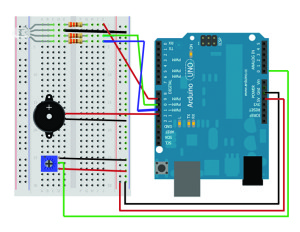
The following diagram shows how to assemble the parts on the breadboard:

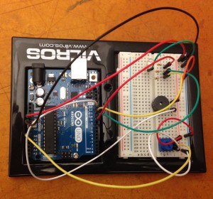
Your final assembly should be something like this:
Code:
Please note that your Arduino must not be connected to the computer. Otherwise, the power might damage or burn out the parts. The code is as follows and next to each part it is explained what each part does.
|
1 2 3 4 5 6 7 8 9 10 11 12 13 14 15 16 17 18 19 20 21 22 23 24 25 26 27 28 29 30 31 32 33 34 35 36 37 38 39 40 41 42 43 44 45 46 47 48 49 |
//BUZZER REACTS TO A SPECIFIC RGB LED COLOR: //Mohammad Momenabadi int red = 9; //Digital pin9 for red led int green = 10; //Digital pin10 for green led int blue = 11; //Digital pin11 for blue led // This verifies the pins for RGB led light on the board int sound = 12; //Digital pin for piezo buzzer int sensorpin = 0; // The potentiometer is connected to analog pin 0 int sensorValue = 0; //introducing vriable void setup() //method runs once, when the sketch starts { pinMode(red, OUTPUT); // initialize the digital pin as an output pinMode(green, OUTPUT); pinMode(blue, OUTPUT); pinMode(sound, OUTPUT); Serial.begin(9600); //initialize serial communication at 9600 bits per second } void loop() // the loop() method runs over and over again { sensorValue = analogRead(sensorpin); // read the value from the sensor Serial.println(sensorValue); // print out the value you read if (sensorValue > 0 && sensorValue <=200)//if voltage value is between 0 and 200, do next step { analogWrite(blue, 000); analogWrite(red, 255); //turn the red light on analogWrite(green, 000); digitalWrite(sound, HIGH); //Piezo sing } else { analogWrite(blue, 000); analogWrite(red, 000); analogWrite(green, 255);//turn the green light on digitalWrite(sound, LOW);//Piezo silence } } |
Now to see the result, plug in your Arduino, upload your code and tern the potentiometer. The result should be like this video:
Video
Many thanks.

It is showing error in the code ,
it says gt is not specified
how to rectify?
I m using RGB color sensor(adc output sensor). I want to detect the blue color using Arduino code..can u plz give me the solution